


Selecting the right size for GFRP angles depends on three factors: load capacity, dimensions, and environmental conditions. Getting sizing wrong carries real risks. Undersized angles may fail under stress, while oversized options waste money and add unnecessary weight. Fiberglass angles offer a favorable strength-to-weight ratio, resist corrosion, and generally require less maintenance than steel. A reliable choice starts with evaluating the loads placed on the structure. Next, engineers compare leg dimensions and thickness against project demands. Finally, they assess site conditions such as chemical exposure and moisture. Following this checklist helps prevent common mistakes and ensures dependable support. This guide provides a clear path forward for structural applications.
Choose GFRP angle size based on load, dimensions, and environment.
Undersized angles may fail; oversized angles waste money and weight.
Check span tables and apply safety factors for load capacity.
Thickness drives bending strength; pick the thinnest that passes.
Match leg length to connection details for bolts or bonding.
Select resin type for chemical resistance and UV stability.
Follow a three-step process: define, review, and validate.
Avoid common mistakes like ignoring deflection and choosing on price alone.
Load and Stress Requirements for GFRP Angles
Engineers must understand how forces travel through each angle before choosing a size. The load direction and angle orientation determine which leg carries the stress. Fiberglass angle profiles come in many dimensions; geometry must match demand.
Types of Loads
Dead vs. Live Loads
Dead loads include permanent weights such as walkway panels, cable trays, and the angle's own mass. These values stay constant over time.
Live loads change over time. Workers, stored equipment, or water buildup count. An engineer adds dead and live values to find the total design load. This sum drives the selection of leg dimensions. A platform holding heavy pumps generally needs a larger angle than one supporting only its own weight.
Dynamic and Cyclic Loads
Dynamic loads arrive suddenly. Equipment vibration, wind gusts, or running personnel create impact forces that may exceed static calculations.
Cyclic loads repeat many times. Each repetition creates microscopic stress that may grow into cracks over time. For FRP structural shapes under cyclic conditions, design charts recommend higher safety margins. The load direction relative to the pultrusion axis also matters for long-term durability.
Calculating Load Capacity
Span Tables and Manufacturer Data
Manufacturers publish span tables for standard FRP angles. These tables show the maximum recommended load for specific profile sizes. The values below represent typical pultruded equal-leg angles (approximately 50×50×6 mm) in simple support at 23°C, for reference only—actual capacity varies by manufacturer and resin system.
| Span (m) | Maximum Recommended Load (kg) | Deflection at Max Load (mm) |
|---|---|---|
| 0.5 | 450 | 2.1 |
| 1.0 | 225 | 4.3 |
| 1.5 | 150 | 7.6 |
| 2.0 | 110 | 10.2 |
Longer spans reduce allowable load significantly. A 2.0-meter span carries roughly one-quarter of a 0.5-meter span for the same profile. Deflection grows with span, so stiffness often governs design rather than ultimate strength.
Safety Factors and Deflection Limits
Safety factors protect against uncertainty in materials, fabrication, and field conditions. The ASCE Pre-Standard for Pultruded Fiber-Reinforced Polymer recommends specific multipliers for each design condition.
| Design Condition | Recommended Safety Factor |
|---|---|
| Static Ultimate Strength | 2.5–3.0 |
| Buckling Stability | 3.0–4.0 |
| Fatigue / Cyclic Loading | 4.0–5.0 |
| Chemical Exposure (additional) | ×1.2–1.5 |
Engineers divide material strength by these factors. Deflection limits come from serviceability rather than failure. Excessive sag can damage attached components and create unsafe walking surfaces.
Matching Stress to Thickness
How Thickness Affects Strength
Thickness raises the section modulus, which controls bending stress. A 6 mm thick angle generally resists bending better than a 3 mm angle of the same leg length.
The thicker member spreads stress across more material. This can reduce peak stress at the corner where angles often fail. Weight increases with thickness; engineers balance strength against mass.
Equal vs. Unequal Leg Angles
Equal-leg angles provide symmetrical strength. They suit frames and brackets where forces come from several directions.
Unequal-leg angles offer more material on one side, such as a longer vertical leg for bolting to columns. Choose based on connection details and how the member aligns to the applied force.
How to Choose Fiberglass Angle Sizes for Structural Support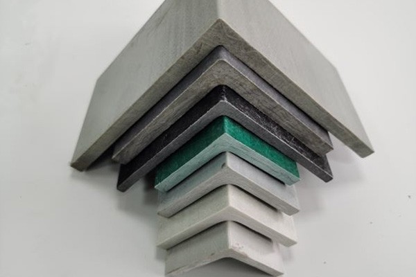
Selecting GFRP angles begins with three geometry decisions: thickness, leg width, and length. Each decision changes how the angle carries force and fits the final structure. A clear sizing method saves money and helps prevent failure. NHC GRP Angles range from 25×25×3 mm to 100×100×10 mm, with custom options available for special projects.
Thickness — The Primary Strength Driver
Common Thicknesses and Applications
Thickness selection drives bending strength more than any other dimension. A thicker wall raises the section modulus, which lowers peak stress under load. Standard pultruded profiles follow general patterns. Small angles, such as 25×25 mm and 30×30 mm, often use 3 mm or 4 mm walls. Medium angles, including 40×40 mm and 50×50 mm, typically carry 4–6 mm or 5–8 mm walls. Large sections like 100×100 mm and 150×150 mm may use 8–12 mm walls for platforms and roof supports. FRP material generally resists corrosion well, so additional surface protection is often unnecessary in moderate environments.
| Profile | Standard Size (mm) | Wall Thickness (mm) |
|---|---|---|
| FRP Angle Profile 1 | 40 × 40 | 4–6 |
| FRP Angle Profile 2 | 50 × 50 | 5–8 |
Balancing Strength and Weight
Thicker angles weigh more. The equal-leg catalog range typically spans 25×25 mm through 152×152 mm, with masses from approximately 0.3 kg/m to 6 kg/m depending on size and resin. Extra mass adds dead load and raises cost. Designers compare the required moment against the available section and pick the thinnest option that passes the safety factor. Resin choice also alters FRP performance. NHC builds profiles with pultrusion technology using ISO polyester, vinyl ester, epoxy, or phthalic acid resin, reinforced with fiberglass or carbon-glass hybrid. A vinyl ester part generally withstands chemical attack better, so it may be preferred in corrosive service. Standards such as EN 13706-1/2/3 [1] define E17 and E23 grades, which let specifiers compare sections without extra testing. Good fiberglass angle selection always balances load demand, environmental resistance, and cost. NHC GRP Angles carry ISO 9001, ISO 14001, and ISO 45001 certification.
Width and Leg Length
Leg Length for Bolted or Bonded Connections
Leg length controls fastener placement. Bolted joints require enough edge distance so the bolt does not tear through the laminate. Bonded joints need sufficient surface area for structural adhesive. Equal-leg angles come as standard stock from 25×25 mm up to 152×152 mm, with multiple catalog sizes. Unequal-leg angles are often custom shapes; common sizes include 75×50, 100×75, and 150×100 mm. Angle leg size selection starts at the connection detail. A designer asks whether the flange needs a longer leg for bolts or a shorter leg for a tight envelope. Leg size and thickness together determine the true capacity of the member.
Width for Surface Area and Stiffness
Width raises the moment of inertia, which improves stiffness. A wider leg resists deflection and spreads bearing loads over more material. Leg width considerations also affect clearance and appearance. A 50×50×6 mm angle generally handles a walkway ledge better than a 40×40×4 mm angle on the same span. The second leg width matters too, because unbalanced sections can twist under off-center loads. Engineers compare both legs when the force direction remains uncertain.
Length and Cut-to-Size Options
Standard Stock vs. Custom Cuts
Pultruded fiberglass angles arrive in standard strip lengths. Most projects need specific lengths. A buyer ordering cut pieces should send the total quantity with cut lengths, the section drawing or catalog number, resin and performance requirements, and the destination port. Standard catalog sections may carry a minimum order quantity by profile; below that limit, suppliers may apply a small-batch premium. Custom cross-section shapes typically require a first-run minimum. The range of components and sizes includes small 25×25×3 mm strips for cable tray supports and large 100×100×10 mm members for bridge railings. This range covers many common FRP structural shapes.
Expansion and Installation Tolerances
Fiberglass-reinforced plastic has a higher coefficient of thermal expansion than steel in the transverse direction, though expansion along the fiber axis is relatively low. Installers should leave a small gap at fixed ends to accommodate thermal movement. ASTM D3917 [2] defines dimensional tolerances for pultruded profiles, so field measurements stay within acceptable limits. Cut length should allow for bolt clearance and shim adjustments. Forcing an oversized angle into a tight bay can create stress points. The assembly performs better when each member fits freely and rests evenly on its bearing surface.
Need Help Selecting the Right GFRP Angle Size?
NHC offers GRP angles from 25×25×3 mm to 100×100×10 mm with custom resin options. Contact their technical team for load calculations, resin selection guidance, and custom cut-to-size quotations.
Request Technical Consultation & QuoteEnvironmental and Durability Factors for Fiberglass Angles
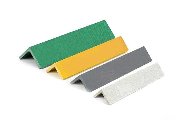
Engineers choose fiberglass angles for demanding sites because they offer corrosion resistance, need relatively little maintenance, and weigh less than steel. NHC GRP Angles provide weather and chemical resistance, UV stability, thermal and electric insulation, and halogen-free fire retardancy. The profiles are non-sparking, relatively easy to assemble, and can perform well in harsh service. Common applications include offshore platforms, water treatment facilities, sewage plants, cooling towers, cable trays, and bridges. The site environment still controls the final size and resin system.
Corrosion and Chemical Exposure
Standard GFRP vs. Enhanced Resin
The resin matrix determines how well an angle survives chemical exposure. Standard polyester handles freshwater and atmospheric service but degrades more rapidly under continuous immersion. Vinyl ester generally resists acids and chlorinated compounds better than polyester. For severe service, proper resin selection often matters more than leg size.
| Material | Marine Rating | Acid/Alkali Rating | Splash-Zone Service Life (Typical) | Chemical-Plant Service Life (Typical) |
|---|---|---|---|---|
| FRP (GFRP, vinyl ester) | Good – inert | Good (vinyl ester) | 25–40+ years (proper spec) | 15–30 years (depends on chemistry) |
| Galvanized steel | Poor – rapid corrosion | Poor – chemical attack | 5–10 years | 3–7 years |
Hydrothermal aging studies at elevated temperatures show that polyester composites may absorb more water through matrix cracking over time. Vinyl ester composites generally retain higher interlaminar shear strength. Seawater exposure can cause pitting and blistering in both materials, though vinyl ester typically degrades less.
How Aggressiveness Affects Thickness
Chemical aggressiveness can influence thickness choice. A thin wall gives chemicals a shorter path to the glass fibers.
Engineers respond by raising the safety factor, often 1.2–1.5 times for chemical exposure, and by selecting a heavier profile or more resistant resin. Extra thickness can delay chemical diffusion and lengthen service life, but adds cost and weight.
Temperature and UV Exposure
Thermal Expansion and Fit
Fiberglass-reinforced plastic has different thermal expansion characteristics than steel. Rigidly fixed ends without adequate clearance can experience stress on hot days. Installers should leave expansion gaps where appropriate.
The insulating nature of GFRP angles can also help protect attached components from thermal stress.
UV Stabilization and Long-Term Performance
Sunlight can degrade unprotected composite surfaces over time. NHC FRP profiles include UV stabilizers that help maintain surface integrity during extended outdoor exposure. However, prolonged intense UV exposure can still cause surface chalking or gloss loss over many years, even with stabilizers.
ASTM B117 salt-spray testing can exceed 5,000 hours with no blistering for certain vinyl ester FRP formulations under controlled laboratory conditions. By comparison, galvanized steel may lose approximately 5–7 µm of zinc coating per year in coastal zones.
Moisture and Freeze-Thaw Cycles
Water Absorption and Dimensional Stability
All composites absorb some moisture. Vinyl ester laminates generally absorb less because their matrix resists micro-cracking better. Lower water uptake helps reduce freeze-thaw damage and keeps dimensions more stable.
At elevated temperatures, composite types may reach a weight-gain maximum followed by weight loss due to matrix degradation. Service temperature also guides resin choice.
Designing for Wet or Marine Environments
GFRP does not create a galvanic reaction with saltwater or dissimilar metals, which is a significant advantage over steel fasteners in marine environments. Coastal structures using properly specified vinyl ester FRP profiles can achieve 25–40+ years of service with appropriate maintenance.
This is why GFRP angles appear on offshore platforms, cooling towers, and sewage plants. Designers typically specify vinyl ester for immersion or severe splash service and polyester for drier interior use.
Step-by-Step Selection Process for FRP Structural Shapes
A disciplined workflow separates successful fiberglass angle selection from guesswork. Engineers who follow a three-step process—define requirements, review specifications, and validate choices—are more likely to select the right member.
Step 1—Define Requirements
Load, Span, and Support Conditions
Engineers begin by listing every load the member will carry. Dead loads include permanent weights. Live loads include workers and equipment. Dynamic loads arrive suddenly from wind gusts or moving machinery. Cyclic loads repeat thousands of times and demand higher safety margins. Load direction determines which leg of the angle carries the highest stress. A force pressing straight down on one leg creates a different response than a pull acting sideways. The engineer should mark the true load direction on a sketch before opening any catalog.
Span length matters equally. Longer spans lower allowable load and increase deflection. A standard pultruded angle (approximately 50×50×6 mm) spanning 0.5 meters may carry roughly 450 kilograms at a simple-support test condition. The same profile spanning 2.0 meters may carry only about 110 kilograms. A fixed end resists rotation; a simply supported end does not. Cantilevers generally need much larger sections than simple spans because the bending moment concentrates at the fixed end.
Environmental and Safety Criteria
The installation site sets the resin system and the safety factor. A dry warehouse interior may allow a standard polyester profile. A coastal walkway generally demands vinyl ester resin to resist saltwater. Chemical splash zones may require an additional safety multiplier of 1.2 to 1.5. ASCE guidance recommends a static ultimate strength factor of 2.5 to 3.0 and a buckling stability factor of 3.0 to 4.0. Fatigue conditions may push the factor to 4.0 to 5.0. Engineers should document all design requirements and dimensions at this stage.
Step 2—Review Specifications
Reading Load Tables Correctly
Catalog load tables provide a starting point, not a final answer. Engineers must verify the test conditions behind each published value. Confirm the deflection limit used to calculate the maximum load. The 0.5-meter span carrying 450 kilograms at 2.1 millimeters deflection is a specific test condition for a specific profile, not a universal rating. Engineers must divide the published load by the project's safety factor before comparison with actual demand. A section that passes a raw table check can still fail once the safety margin is applied.
Comparing Resin Types and Fiber Architectures
Many FRP structural shapes come with different resin matrices and fiber architectures. Standard ISO polyester handles dry indoor service and light chemical exposure. Vinyl ester generally resists acids, chlorinated compounds, and saltwater better. The reinforcement also varies. Continuous fiberglass rovings provide stiffness along the pultrusion axis. Carbon-glass hybrids can raise the modulus where deflection is critical. NHC manufactures its GRP angles with these options using pultrusion technology. The catalog range from 25×25×3 mm to 100×100×10 mm covers many structural requirements, but the resin choice determines whether that size survives its environment.
Step 3—Validate Your Choice
When to Consult a Structural Engineer
A structural engineer should review any large or heavily loaded installation. Complex geometries, long spans, and high safety classes require FRP structural design calculations beyond simple catalog lookup. The engineer checks buckling resistance, torsional response, and connection capacity. They also verify that the selected leg dimensions match the bolt edge distances and bond areas. Skipping this review can create hidden liability. An undersized angle may pass a quick span check yet buckle under a concentrated point load.
Field Checks and Prototype Testing
Field checks can catch problems that drawings miss. Lay the fiberglass angles on the actual supports before final installation. Check that bolt holes align with structural support frames and that edge distances meet the manufacturer's minimum. Confirm the GFRP angles fit freely in the intended envelope. If the project allows, install one prototype member and measure its deflection under real load. The measured value should fall within the calculated limit. This test also reveals installation tolerances, thermal expansion gaps, and shim requirements. NHC supports this validation phase with tailored services, fast response, and after-sales support. Their team can assist with custom dimensions and resin selection. This partnership helps ensure the final fiberglass angle sizing matches the project's actual working conditions.
A clear process helps protect against undersized failures and oversized costs. Define the requirements honestly. Review the specifications carefully. Validate the selection with engineering and field testing. Each step reduces uncertainty, and every uncertainty removed makes the final FRP sizing decision safer. No single sizing shortcut replaces this process.
Common Mistakes to Avoid
Even experienced designers can make sizing errors with GFRP angles. Undersized members risk structural failure. Oversized members waste money and add unnecessary weight. Three mistakes cause many problems: ignoring deflection, overlooking connections, and choosing on price alone.
Ignoring Deflection Limits
Why Stiffness Matters
Many engineers check only strength and ignore deflection until a structure sags. Serviceability limit states often govern walkway and platform design before tensile strength is reached.
These states include short-term deflection, creep under sustained load, shear and local buckling, connection behavior, stability, bearing, and joint design. A member can pass every strength calculation yet deflect too far under routine use.
Serviceability Issues from Excessive Deflection
Excessive deflection can create safety hazards. Bouncy walkways feel unstable and may alarm occupants. Grating spans between supports should comply with code-defined deflection limits.
Engineers can minimize deflection by optimizing span lengths, increasing member stiffness, and adding intermediate supports. Checking deflection early helps prevent costly redesigns after installation.
Overlooking Connection Details
Bolt Hole Sizes and Edge Distances
Connections can fail more often than the angles themselves. Mismatched bolt holes and inadequate edge distances can cause premature joint failure. Pultruded FRP connections generally require a minimum edge distance of 2.0 bolt diameters, rising to 3.0 diameters in the pull direction for cleavage-critical joints. End distance under tension in a single row typically requires 4.0 diameters; edge distance may need only 1.5 diameters. Pitch and row spacing should reach 4.0 diameters.
Workers should drill holes 1.0–1.5 mm oversize. Sharp bits with a backing scrap plate help prevent breakout. Resin sealing can protect cut edges in corrosive environments. Punching holes through unbacked laminate can split plies invisibly, creating joints that pass initial tests but may fail in service.
Galvanic Corrosion Risks
Fiberglass angles are highly corrosion-resistant and do not rust like steel. However, metal fasteners used with GFRP can create galvanic risks in saltwater and humid environments.
Designers may specify non-conductive washers or isolation barriers between GFRP members and steel bolts, and resin-seal holes in reversed-load connections.
Choosing Size Based on Cost Alone
Hidden Costs of Undersized Angles
A cheaper, thinner angle may look economical initially. Hidden costs can appear later. Failure studies show that poor design and sloppy manufacturing can compromise structural integrity.
Irregular thickness can create weak spots at reinforced joints. Inadequate thickness at stress-intensification zones may cause rupture. Improper fiber orientation and poor fiber-matrix interfaces can also contribute to failure.
Why Cheaper Isn't Always Better
The lowest initial bid rarely produces the lowest lifetime cost. A thin angle may fail early, forcing replacement and downtime. An oversized angle wastes material but rarely fails.
A balanced FRP selection weighs first cost against expected service. A properly sized fiberglass angle helps prevent premature failure. Paying a little more upfront can help avoid the larger cost of structural collapse or early replacement.
Choosing the right GFRP angles demands attention to load, dimensions, and environment. These three factors work together; none can stand alone. A member sized correctly for weight may still fail in a corrosive setting. Informed fiberglass angle selection starts with honest requirements. Engineers review specifications and validate choices with field checks. This process helps prevent common errors. Ignoring deflection limits can cause sagging structures. Choosing based on price alone may lead to premature failure. A reliable source of fiberglass angles matters too. Fiberglass-reinforced plastic performs well when properly specified. Manufacturing support reduces risk. NHC delivers quality products and technical guidance across many applications. Trusted partners help FRP projects succeed. Careful sizing today can save cost and downtime tomorrow.
FAQ
How does an engineer determine the correct fiberglass angle size for a walkway?
The engineer calculates total dead and live loads first. Then they check span tables and apply the appropriate safety factor. Deflection limits often govern walkway design. A 50×50×6 mm angle at 0.5-meter span may carry approximately 450 kg, while the same profile at 2.0-meter span carries only about 110 kg. Stiffness matters as much as strength.
What thickness works best for chemical plant applications?
Vinyl ester resin generally resists acids and chlorinated compounds better than standard polyester. Engineers may add a safety multiplier of 1.2 to 1.5 for chemical exposure. A thicker profile can delay chemical diffusion and extend service life. The extra weight and cost may be justified by a longer replacement cycle, depending on the specific chemical environment.
Can installers cut GFRP angles on site?
Yes. Pultruded profiles arrive in standard strip lengths and accept field cuts. Workers should use sharp bits with a backing scrap plate to prevent breakout. Resin sealing can protect cut edges in corrosive environments. Custom cuts require accurate measurements and allowance for bolt clearance and thermal expansion gaps.
Why do fiberglass angles need expansion gaps during installation?
Fiberglass-reinforced plastic has different thermal expansion characteristics than steel. Rigidly fixed ends without adequate clearance can experience stress on hot days. Installers should leave a small gap at fixed ends to accommodate thermal movement. ASTM D3917 defines dimensional tolerances for pultruded profiles, so field measurements stay within acceptable limits.
What is the minimum edge distance for bolts in pultruded FRP angles?
Pultruded connections generally require a minimum edge distance of 2.0 bolt diameters. This may rise to 3.0 diameters in the pull direction for cleavage-critical joints. End distance under tension in a single row typically requires 4.0 diameters. Workers should drill holes 1.0–1.5 mm oversize for proper fit.
How does UV exposure affect long-term performance?
Sunlight can degrade unprotected composite surfaces over time. NHC FRP profiles include UV stabilizers that help maintain surface integrity during extended outdoor exposure. ASTM B117 salt-spray testing can exceed 5,000 hours with no blistering for certain formulations. Galvanized steel may lose about 5–7 µm of zinc coating per year in coastal zones, so fiberglass generally offers better durability in such environments.
When should a project manager consult a structural engineer?
A structural engineer should review any large or heavily loaded installation. Complex geometries, long spans, and high safety classes require design calculations beyond simple catalog lookup. The engineer checks buckling resistance, torsional response, and connection capacity. Skipping this review can create hidden liability and potential failure.
What is the most common sizing mistake with GFRP angles?
Ignoring deflection limits ranks as a frequent error. A member can pass every strength calculation yet sag too far under routine use. Bouncy walkways feel unstable and may alarm occupants. Engineers can minimize deflection by optimizing span lengths, increasing member stiffness, and adding intermediate supports.